
VIP member
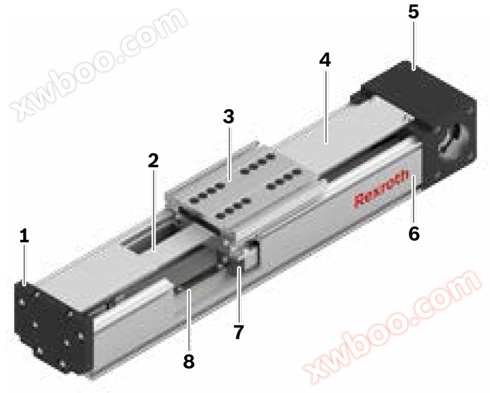
Functional Module FMB Calculation (Drive Design) of Rexroth Linear Module
Functional Module FMB Calculation (Drive Design) of Rexroth Linear Module
Product details
Drive Design
foundation
When designing the drive, the total power component can be divided into mechanical device and drive device parts.mechanical devicePart of it includes linear system components and transmission parts (reducers or directly without transmission parts) as well as considering the load. The combination of motor control unit and corresponding functional data is called electricdrive system.
The design or size definition of the electric drive device is based on the reference point of the motor shaft. When designing the driver, it is necessary to consider the limit and basic values. Must comply with the limit values to prevent damage to mechanical components.

Technical data and formula symbols for mechanical devices
Corresponding maximum allowable driving torque and speed limits, as well as basic values of friction torque and moment of inertia, must be used for all components (linear systems, reducers)! Drive data. When considering the basis of drive design, the following technical data and their corresponding formula symbols are used for the mechanical device part. The data in the table are all listed in the "Technical Data" section or calculated using formulas on subsequent pages.
|
|
mechanical device |
|||
|
load |
linear system |
Transmission components reducer |
||
|
moment of gravity |
(Nm) |
Mg 5) |
— |
— |
|
friction torque |
(Nm) |
—4) |
MRs 3) |
MRge 3) |
|
moment of inertia |
(kgm2) |
Jt 1) |
Js 2) |
Jge 3) |
|
*Maximum allowable speed |
(m/s) |
— |
vmax 3) |
— |
|
*Permissible rotational speed |
(rpm) |
— |
np 1) |
nge
|


Online inquiry
-
Contacts
-
Company
-
Telephone
-
Email
-
WeChat
-
Verification Code
-
Message Content
-