
VIP member
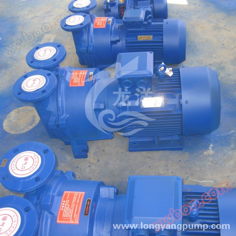
2BV (SKA) series water ring vacuum pump
Release time: 2014-1-7 15:36:48 Brand: Longyang Pump Valve model: 2BV (SKA) Material: Cast Iron, Stainless Steel Speed: 2880, 1450, 1430, 970 r/min Ul
Product details
1 Product Overview
The 2BV water ring vacuum pump is suitable for extracting gases and water vapor, and the suction pressure can reach 33mbar absolute pressure (97% vacuum degree). When using transformer oil as the working fluid (called oil ring vacuum pump), the suction pressure can reach 6.7mbar absolute pressure (99.3% vacuum degree), which can completely replace reciprocating vacuum pumps. When the liquid ring vacuum pump operates for a long time under the suction pressure approaching the limit vacuum, a cavitation protection tube should be connected to protect the pump and eliminate cavitation noise. When used as a compressor, its pressure reaches 0.26MPa (absolute pressure). When used as a compressor, the increase in exhaust pressure will cause an increase in the power of the 2BV pump. When ordering, the exhaust pressure should be specified to select the appropriate motor power.
As a new generation of energy-saving products, the 2BV water ring vacuum pump will fully replace the SK, 2SK series water ring vacuum pumps and W, WY, WL series reciprocating vacuum pumps with excellent performance and numerous advantages.
The 2BV2 Ex and 2BV6 series water ring vacuum pumps/compressors are mainly used for extracting explosive gases and working in various flammable and explosive environments. Their performance parameters are the same as the corresponding models of the 2BV2 and 2BV5 series.
The 2BV series stainless steel vacuum pump can be used in various occasions with high corrosion resistance requirements and high cleanliness requirements. According to the working conditions, all overcurrent components of the 2BV series stainless steel vacuum pump, including the pump body, pump cover, disc, and impeller, can be made of various stainless steel materials such as SUS304 (0Cr18Ni9), SUS316 (0Cr17Ni12Mo2), SUS316L (00Cr17Ni14Mo2), etc. The pump shaft material is 2Cr13 or 0Cr18Ni12Mo2Ti. The mechanical seal of the 2BV water ring vacuum pump adopts imported products, and the seal can be made of fluororubber or polytetrafluoroethylene.
2 Product Features
1. The 2BV water ring vacuum pump has a coaxial direct connection design, which saves space and is easy to install.
2. All 2BV water ring vacuum pumps are equipped with imported mechanical seals as standard.
3. All 2BV water ring vacuum pumps are equipped with cavitation protection pipe interfaces. If working under extreme pressure, opening the cavitation protection pipe interface (or connecting it to the separator) can eliminate cavitation noise while ensuring maximum suction effect and protect the pump.
4. The aluminum bronze impeller has high strength, durability, and improves the corrosion resistance of the 2BV water ring vacuum pump. If the overcurrent components are made of stainless steel material, they can work in more demanding environments.
5. The unique flexible exhaust port design prevents over compression, ensuring that the 2BV water ring vacuum pump is within its performance range.
6. All use Y2 series motors with protection levels of IP54 and IP55 (usually IP44)
7. All 2BV water ring vacuum pumps use NTN or NSK imported bearings
2. All 2BV water ring vacuum pumps are equipped with imported mechanical seals as standard.
3. All 2BV water ring vacuum pumps are equipped with cavitation protection pipe interfaces. If working under extreme pressure, opening the cavitation protection pipe interface (or connecting it to the separator) can eliminate cavitation noise while ensuring maximum suction effect and protect the pump.
4. The aluminum bronze impeller has high strength, durability, and improves the corrosion resistance of the 2BV water ring vacuum pump. If the overcurrent components are made of stainless steel material, they can work in more demanding environments.
5. The unique flexible exhaust port design prevents over compression, ensuring that the 2BV water ring vacuum pump is within its performance range.
6. All use Y2 series motors with protection levels of IP54 and IP55 (usually IP44)
7. All 2BV water ring vacuum pumps use NTN or NSK imported bearings
3 Application field
| Vacuum filtration | (Chemical filtration plant, chemical processing plant, iron ore plant, mining industry, phosphate fertilizer plant, paper mill, poultry processing plant, coal preparation plant) | Steam recovery |
| Water pump intake | ||
| Condenser water tank replenishment | ||
| vacuum distillation | (Milk factory, food factory, chemical factory, pulp mill) | dry |
| Vacuum disinfection | (Hospital, Medical Room, Laboratory) | Wood treatment/drying |
| extrusion molding | (Plastic industry) | Medical/Laboratory Vacuum |
| forming | (Manufacturing of plastics, polyethylene, rubber, tires, etc.) | solvent recovery |
| impregnation | (Food processing, wood processing, textile factories, plywood factories, manufacturing of utility poles, etc.) | Soil purification |
| vacuum packaging | ||
| Liquid degassing | (Food processing, water softening, bottling plant) | extraction |
| Compressed air regeneration | (Pulp, steel, automotive, glass, chemical) | tanning |
| food processing | (Food processing factory, dairy factory) | canned |
4 working principle

Working principle of 2BV series water ring vacuum pump
The impeller 3 of the 2BV water ring vacuum pump is eccentrically installed inside the pump body as shown in the figure above. When starting, a certain height of water is injected into the pump. Therefore, when the impeller 3 rotates, the water is subjected to centrifugal force and forms a rotating water ring 1 on the inner wall of the pump body. The lower inner surface of the water ring is tangent to the hub and rotates in the direction of the arrow. During the first half of the rotation process, the inner surface of the water ring of the 2BV water ring vacuum pump gradually separates from the hub, forming a closed space between the impeller blades and the water ring. As the impeller rotates, the space gradually expands, and the gas pressure in the space decreases. Gas is sucked in from the suction port of the circular disk; During the latter half of the rotation, the inner surface of the water ring gradually approaches the hub, and the space between the blades gradually shrinks. The gas pressure in the space increases, and when it exceeds the pressure at the exhaust port, the gas between the blades is discharged from the disc exhaust port. In this way, every time the impeller rotates, the space between the blades sucks and exhausts once, and many spaces work continuously. The 2BV water ring vacuum pump continuously sucks or compresses gas.
The 2BV water ring vacuum pump generates heat during operation, which causes the working water ring to heat up. At the same time, some water and gas are expelled together. Therefore, during operation, it is necessary to continuously supply water to the pump to cool and replenish the water consumed inside the pump, in order to meet the working requirements of the pump.
When the gas discharged from the 2BV water ring vacuum pump is no longer used, a gas water separator is connected to the exhaust port of the 2BV water ring vacuum pump. After the exhaust gas and some of the carried water are discharged into the gas water separator, the gas is separated and the gas is discharged through the exhaust pipe. The remaining water is supplied to the pump through the return pipe for continued use. With the extension of working hours, the temperature of the working water will continue to rise. At this time, cold water needs to be supplied from the water supply pipe to reduce the temperature of the working water and ensure that the pump can meet the required technical requirements and performance indicators.
When the 2BV water ring vacuum pump is used as a compressor, the pump exhaust port is connected to a gas water separator. The gas water mixture enters the gas water separator and is automatically separated. The gas is transported to the required system through the exhaust pipe, and the working water enters the 2BV water ring vacuum pump through the separator. When compressing gas, the working water is extremely hot, and the water is discharged from the pump exhaust port, causing the temperature to increase. Cold water needs to be continuously supplied from the water supply pipe to replenish the released water and also serve as a cooling effect, so that the working water temperature does not become too high, thereby ensuring the performance of the compressor, meeting technical specifications, and meeting process requirements.
5 Structural diagram explanation

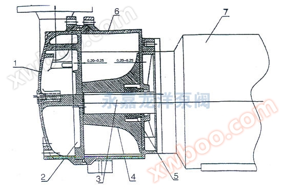
Structural diagram of 2BV2-060/061/070/071 water ring vacuum pump
1. Pump cover 2. Circular disc 3. Flat key 4. Impeller 5. Mechanical seal 6. Pump body 7. Electric motor
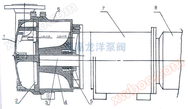
Structural diagram of 2BV5-110/111/121/131/161 water ring vacuum pump
1. Pump cover 2. Circular disc 3. Flat key 4. Impeller 5. Mechanical seal 6. Pump body 7. Electric motor
Structural diagram of 2BV6-110/111/121/131/161 water ring vacuum pump
1. Pump cover 2. Circular disc 3. Flat key 4. Impeller 5. Mechanical seal 6. Pump body 7. Electric motor
The 2BV vacuum pump consists of pump cover, pump body, disc, impeller, mechanical seal, motor and other components. The intake and exhaust pipes of the 2BV vacuum pump are connected to the pump chamber through the suction and exhaust holes installed on the disc on the pump cover. The shaft is eccentrically installed in the pump body, and the impeller is fixed on the shaft with a flat key. The partial clearance between the two end faces of the 2BV vacuum pump is adjusted by the pad between the pump body and the disc. The clearance between the impeller and the disc on the pump cover is adjusted by the pad between the disc and the pump body. The clearance between the two end faces of the impeller and the disc on the pump cover determines the size and ultimate pressure of gas loss in the flow from the intake to the exhaust port in the pump chamber.
The sealing of the 2BV vacuum pump adopts mechanical seal, which is installed between the impeller and the pump body. The gap between the impeller and the pump body is determined by a mechanical seal. A disc is installed on the cover of the 2BV vacuum pump, which is equipped with suction and exhaust holes and flexible exhaust valve plates. The function of the flexible valve plate is to discharge the gas before the exhaust port when the gas pressure between the impeller blades reaches the exhaust pressure, reducing the power consumption caused by excessive gas pressure and thus reducing the rate of consumption.
6 Model parameter table
| model | Gas volume (m ³/min) | Extreme vacuum (Mpa) | Motor power (kw) |
Pump speed (r.p.m.) | Working fluid flow rate (L/min) | noise (A) |
weight (kg) |
| 2BV2060 | 0.45 | 0.097 | 0.81 | 2880 | 2 | 62 | 37 |
| 2BV2061 | 0.86 | 0.097 | 1.45 | 2880 | 2 | 65 | 41 |
| 2BV2070 | 1.33 | 0.097 | 2.35 | 2850 | 2.5 | 66 | 66 |
| 2BV2071 | 1.83 | 0.097 | 3.85 | 2860 | 4.2 | 72 | 85 |
| 2BV5110 | 2.75 | 0.097 | 4 | 1450 | 6.7 | 63 | 120 |
| 2BV5111 | 3.83 | 0.097 | 5.5 | 1450 | 8.3 | 68 | 150 |
| 2BV5121 | 4.66 | 0.097 | 7.5 | 1450 | 10 | 69 | 210 |
| 2BV5131 | 6.66 | 0.097 | 11 | 1430 | 15 | 73 | 280 |
| 2BV5161 | 8.33 | 0.097 | 15 | 970 | 20 | 74 | 390 |
7 performance curve graph

Performance Curve of 2BV Series Water Ring Vacuum Pump
8 Outline and installation dimension diagram

Outline dimension drawing of 2BV2 water ring vacuum pump
| model | A | B | B1 | E | H1 | H2 | H3 | H4 | H6 | M |
| 2BV2060 | 455 | 186 | 140 | 100 | 90 | 118 | 126 | 195 | 37.5 | 244 |
| 2BV2061 | 476 | 186 | 140 | 100 | 90 | 118 | 126 | 195 | 37.5 | 263 |
| 2BV2070 | 545 | 223 | 160 | 140 | 100 | 128 | 146 | 222 | 33 | 280 |
| 2BV2071 | 566 | 223 | 190 | 140 | 112 | 140 | 158 | 234 | 45 | 309 |
| model | P3 | R | S2 | W1 | W2 | W3 | d | N3.0 | N4.2 | N8.7 |
| 2BV2060 | 180 | 217 | φ10 | 110 | 25.5 | 21 | G1' | G3/8' | G1/4' | G3/8' |
| 2BV2061 | 180 | 236 | φ10 | 110 | 25.5 | 21 | G1' | G3/8' | G1/4' | G3/8' |
| 2BV2070 | 203 | 252 | φ12 | 110 | 33 | 27 | G11/2' | G3/8' | G1/4' | G3/8' |
| 2BV2071 | 225 | 278 | φ12 | 110 | 33 | 27 | G11/2' | G3/8' | G1/4' | G3/8' |
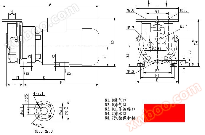
Outline dimension drawing of 2BV5 water ring vacuum pump
| model | A | B | B1 | B2 | C1 | C2 | H1 | H2 | H3 | H4 |
| 2BV5110 | 637 | 325 | 255 | 190 | 41 | 26 | 140 | 156 | 202 | 361 |
| 2BV5111 | 679 | 325 | 265 | 216 | 36 | 26 | 150 | 166 | 212 | 371 |
| 2BV5121 | 771 | 347 | 265 | 216 | 36 | 26 | 150 | 167 | 217 | 385 |
| 2BV5131 | 852 | 377 | 300 | 254 | 35 | 30 | 175 | 194 | 249 | 427 |
| 2BV5161 | 1044 | 479 | 370 | 279 | 30 | 30 | 210 | 225 | 303 | 521 |
| model | H6 | H7 | K | L | F | N | S1 | S2 | T | d1 |
| 2BV5110 | 38 | 57 | 342 | 130 | 464 | 92 | φ12 | φ12 | 340 | 19 |
| 2BV5111 | 48 | 68 | 348 | 130 | 500 | 92 | φ12 | φ12 | 340 | 19 |
| 2BV5121 | 39 | 60 | 430 | 147 | 584 | 97 | φ12 | φ12 | 381.5 | 19 |
| 2BV5131 | 53 | 76 | 477.5 | 147 | 658.5 | 103 | φ15 | φ15 | 381.5 | 19 |
| 2BV5161 | 51 | 80 | 555 | 201 | 808 | 138 | φ15 | φ15 | 450 | 22 |
| model | d3 | d4 | d5 | W1 | W2 | W3 | d | N3.0 | N4.2 | N8.7 |
| 2BV5110 | 123 | 97 | 52 | 180 | 52 | 27 | DN50 | G3/4' | G3/8' | G3/8' |
| 2BV5111 | 123 | 97 | 52 | 180 | 52 | 27 | DN50 | G3/4' | G3/8' | G3/8' |
| 2BV5121 | 142 | 113 | 66.5 | 200 | 57 | 29 | DN65 | G3/4' | G3/8' | G3/8' |
| 2BV5131 | 142 | 113 | 66.5 | 200 | 57 | 29 | DN65 | G3/4' | G3/8' | G3/8' |
| 2BV5161 | 156 | 130 | 80 | 250 | 81 | 41 | DN80 | G3/4' | G3/8' | G3/8' |
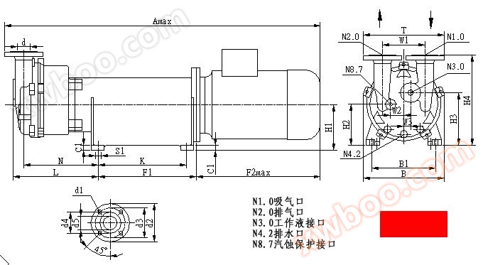
Outline dimension drawing of 2BV6 water ring vacuum pump
| model | Amax | B | B1 | C1 | F1 | F2max | H1 | H2 | H3 | H4 | K | L | N |
| 2BV6110 | 1190 | 325 | 255 | 26 | 291 | 450 | 160 | 173 | 223 | 381 | 250 | 319 | 281 |
| 2BV6111 | 1237 | 325 | 279 | 26 | 360 | 470 | 180 | 196 | 242 | 401 | 320 | 365 | 327 |
| 2BV6121 | 1368 | 347 | 279 | 26 | 360 | 575 | 180 | 197 | 247 | 415 | 320 | 384 | 342 |
| 2BV6131 | 1495 | 377 | 320 | 26 | 461 | 585 | 215 | 234 | 287 | 467 | 414 | 405 | 357 |
| 2BV6161 | 1625 | 479 | 370 | 26 | 461 | 640 | 215 | 230 | 310 | 526 | 414 | 480 | 416 |
| model | W2 | W3 | S1 | T | d1 | d2 | d3 | d4 | d5 | d | N3.0 | N4.2 | N8.7 |
| 2BV6110 | 52 | 27 | φ13 | 340 | 19 | 160 | 123 | 97 | 52 | DN50 | G3/4' | G3/8' | G3/8' |
| 2BV6111 | 52 | 27 | φ13 | 340 | 19 | 160 | 123 | 97 | 52 | DN50 | G3/4' | G3/8' | G3/8' |
| 2BV6121 | 57 | 29 | φ13 | 381.5 | 19 | 182 | 142 | 113 | 66.5 | DN65 | G3/4' | G3/8' | G3/8' |
| 2BV6131 | 57 | 29 | φ15 | 381.5 | 19 | 182 | 142 | 113 | 66.5 | DN65 | G3/4' | G3/8' | G3/8' |
| 2BV6161 | 81 | 41 | φ15 | 450 | 22 | 200 | 156 | 130 | 80 | DN80 | G3/4' | G3/8' | G3/8' |
9 Installation of 2BV water ring vacuum pump equipment
1. Pump installation:
Before long-term parking and operation, it is necessary to rotate the fan blades to confirm whether the 2BV water ring vacuum pump is stuck.
The starting technique for 2BV water ring vacuum pump is as follows:
1. Close the intake valve;
2. Open the exhaust valve;
3. Inject a small amount of water into the pump, taking the water consumption in the technical specifications table as a reference;
4. Start the motor;
5. Open the intake valve;
6. Adjust the water supply to consume a small amount of water and ensure the technical specifications of the pump.
The parking sequence of 2BV water ring vacuum pump is as follows:
1. Close the intake valve;
2. Turn off the motor and stop the water supply at the same time
3. Release the remaining water from the pump body.
Maintenance of 2BV type water ring vacuum pump
1. To avoid wear and tear on the impeller, pump body or main impeller, dust particles that enter the pump chamber with gas and working fluid can be washed away through the flushing port at the lower part of the pump.
2. If using hard water working fluid, the pump must be softened or cleaned with a solution within a certain period of time.
3. The bearing of the motor that works normally should be 15 ℃~20 ℃ higher than the surrounding temperature, and should not exceed 55 ℃~60 ℃. The bearing that works normally should be oiled 1-2 times a year, cleaned at least once a year, and all lubricating oil should be replaced.
4. If there is leakage in the mechanical seal used, the dynamic and static rings of the mechanical seal should be checked for damage or aging of the sealing ring. If the above situation occurs, new parts need to be replaced.
When installing vacuum pumps and compressors, the installation surface must be level and securely fastened with bolts through the bottom corner holes. To prevent welding slag from entering the vacuum pump during installation, suction should be carried out before installation
2. Installation of water separatorThe air-water separator can be directly installed on the exhaust port of the vacuum pump and securely fixed with bolts. The gas water separator has a pipeline connected to the pump, which supplies the water required for the pump to operate. The remaining working water is supplied by the water supply pipeline, and the water supply volume is adjusted by the valve on the pipeline. A check valve should be installed on the intake pipe of a vacuum pump or compressor to prevent water from the vacuum pump or compressor from returning to the system under the pressure of the exhaust pipe during parking.
Starting and stopping of 2BV water ring vacuum pumpBefore long-term parking and operation, it is necessary to rotate the fan blades to confirm whether the 2BV water ring vacuum pump is stuck.
The starting technique for 2BV water ring vacuum pump is as follows:
1. Close the intake valve;
2. Open the exhaust valve;
3. Inject a small amount of water into the pump, taking the water consumption in the technical specifications table as a reference;
4. Start the motor;
5. Open the intake valve;
6. Adjust the water supply to consume a small amount of water and ensure the technical specifications of the pump.
The parking sequence of 2BV water ring vacuum pump is as follows:
1. Close the intake valve;
2. Turn off the motor and stop the water supply at the same time
3. Release the remaining water from the pump body.
Maintenance of 2BV type water ring vacuum pump
1. To avoid wear and tear on the impeller, pump body or main impeller, dust particles that enter the pump chamber with gas and working fluid can be washed away through the flushing port at the lower part of the pump.
2. If using hard water working fluid, the pump must be softened or cleaned with a solution within a certain period of time.
3. The bearing of the motor that works normally should be 15 ℃~20 ℃ higher than the surrounding temperature, and should not exceed 55 ℃~60 ℃. The bearing that works normally should be oiled 1-2 times a year, cleaned at least once a year, and all lubricating oil should be replaced.
4. If there is leakage in the mechanical seal used, the dynamic and static rings of the mechanical seal should be checked for damage or aging of the sealing ring. If the above situation occurs, new parts need to be replaced.
Online inquiry
-
Contacts
-
Company
-
Telephone
-
Email
-
WeChat
-
Verification Code
-
Message Content
-