
VIP member

2X two-stage rotary vane vacuum pump
Release time: 2014-1-5 20:37:25 Brand: Longyang Pump Valve model: 2X Speed: 420-590 r/min Extreme vacuum: 6 × 10 ^ (-2) PA Extraction rate: 2-70 L/S E
Product details
1 Introduction to 2X Double Stage Rotary Vacuum Pump
The 2X vacuum pump is a two-stage structure, consisting of a high-pressure stage and a low-pressure stage. Its suction port is connected to a vacuum container or vacuum equipment, and during operation, a large amount of gas inside the container is sucked in and discharged.
2 Main applications of 2X two-stage rotary vane vacuum pump
l、 One of the basic equipment for gas extraction, it can be used alone or connected with ultra-high vacuum pumps such as booster pumps, diffusion pumps, and molecular pumps as a front-end pump. It is widely used in electronic device manufacturing, vacuum drying, filtration, impregnation, coating, welding, smelting, and laboratory equipment.
2. Under the condition of an ambient temperature range of 5 ℃ to 40 ℃ and an inlet pressure of less than 10 Torr, long-term operation is allowed. When the relative temperature of the extracted gas is greater than 90%, the gas damper should be opened.
3. The continuous opening of the air inlet to the atmosphere should not exceed 3 minutes of operation.
4. Not suitable for extracting gases that corrode metals, react chemically with pump oil, contain particulate dust, as well as gases with high oxygen content, explosiveness, and toxicity.
2. Under the condition of an ambient temperature range of 5 ℃ to 40 ℃ and an inlet pressure of less than 10 Torr, long-term operation is allowed. When the relative temperature of the extracted gas is greater than 90%, the gas damper should be opened.
3. The continuous opening of the air inlet to the atmosphere should not exceed 3 minutes of operation.
4. Not suitable for extracting gases that corrode metals, react chemically with pump oil, contain particulate dust, as well as gases with high oxygen content, explosiveness, and toxicity.
3 The significance of the 2X two-stage rotary vane vacuum pump model

4 Working principle of 2X two-stage rotary vane vacuum pump

| 1 | 高真空室外 | 2 | Intake nozzle | 3 | rotor | 4 | Gas tube | 5 | Exhaust valve |
| 6 | Low vacuum chamber | 7 | rotor | 8 | scraper | 9 | spring | 10 | Exhaust valve |
Figure 1 is a schematic diagram of a rotary vane vacuum pump. The rotors 3 and 7 are tangent to the high vacuum chamber 1 and the low vacuum chamber 6. The rotors 3 and 7 rotate in the direction of the arrows, driving the rotating blades that slide in the rotor slots to rotate. Due to the action of the spring 9 and centrifugal force, the outer end of the blades slides tightly against the inner surface of the high and low vacuum chambers, separating the moon shaped space formed by the rotor and the high and low vacuum chambers from the intake nozzle 2 to the exhaust valve 5 and from the exhaust pipe 4 to the exhaust valve 10, forming two or three volumes with periodic size changes. When the rotary vane vacuum pump continues to rotate in the position shown in the figure, the volumes A and C gradually increase, and the gas being pumped enters the pump through the intake nozzle. At the same time, B and D The sentence is: The volume gradually decreases, the pressure increases, and then the exhaust valves 5 and 10 are opened to discharge the gas outside the vacuum chamber. The gas passes through the oil surface and is discharged into the atmosphere. Because the oil floods the exhaust valve, it can prevent the gas from returning to the vacuum chamber. When the pumping pressure is high, the valves of both the high and low vacuum chambers exhaust, equivalent to a single-stage pump. When the vacuum degree is high, all the gas enters the vacuum chamber and is then discharged through exhaust valve 10. At this time, the two-stage series connection enters the operation of the two-stage pump.
When the extracted gas contains a high amount of vapor gas, when the gas is compressed and the partial pressure of its vapor exceeds the saturation pressure of the vapor at the pump temperature, the vapor is compressed into a liquid, which cannot be discharged by the rotary vane vacuum pump and is mixed in the vacuum oil, greatly reducing the performance of the pump. If an appropriate amount of air is added, so that the partial pressure of the steam when compressed is also lower than the saturation pressure of the pump temperature, the steam can be discharged from the pump before becoming liquid. Therefore, pumps above 2X-4 in this series are equipped with a gas mixing valve 11 that can accommodate a certain amount of gas, as shown in Figure 1
5 Performance parameters of 2X two-stage rotary vane vacuum pump
| 2X two-stage rotary vane vacuum pump | 2X-2 | 2X-4A | 2X-8A | 2X-8 | 2X-15A | 2X-15 | 2X-30 | 2X-70 | ||
| 2 | 4 | 8 | 15 | 30 | 70 | |||||
| ultimate vacuum | Guanqi Town Kaiqi Town |
PA (Torr) | 6.0×10⁻²(≤5×10⁻³)110 | |||||||
| 6.0×10⁻¹(≤5×10⁻³) | (≤1×10) | |||||||||
| Electric motor power (KW) | 0.37 | 0.55 | 1.1 | 1.5 | 3 | 5.5 | ||||
| Temperature rise (℃) | ≤40 | |||||||||
| Inlet diameter (mm) | 18 | 25 | 40 | 40 | 65 | 80 | ||||
| Speed (r/min) | 450 | 590 | 420 | |||||||
| Oil consumption (L) | 0.7 | 1.0 | 2.0 | 2.8 | 3.0 | 4.2 | ||||
| Noise dB (A) | 68 | ≤68 | ≤70 | ≤75 | ≤78(~70) | ≤80(~75) | ||||
| Dimensions (cm) | 56×31×39 | 56×34×37 | 79×43×54 | 79×53×54 | 78×50×56 | 91×65×70 | ||||
| Applicable solenoid valve models | DDC-JQ25 | DDC-JQ40 | DDC-JQ65 | DDC-JQ80 | ||||||
| Weight (kg) | 58 | 55 | 80 | 110 | 232 | 330 | ||||
| cooling method | natural cooling | water cooling | Naturally cold | water cooling | ||||||
| Cooling water volume (L/min) | - | >0.5 | - | >0.8 | >1 | >2 | ||||
6 Installation dimensions of 2X two-stage rotary vane vacuum pump
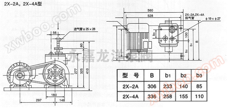
Installation dimension diagram of 2X-2A, 2X-4A two-stage rotary vane vacuum pump

Outline and Installation Dimensional Drawing of 2X-8,2X-15 Double stage Rotary Vacuum Pump

Installation dimension diagram of 2X-30A, 2X-70A two-stage rotary vane vacuum pump

2X-4A type (new) two-stage rotary vane vacuum pump external installation dimension diagram

Installation dimension diagram of 2X-4B two-stage rotary vane vacuum pump
7 Technical parameter table of 2X two-stage rotary vane vacuum pump
| Code model | φD1 | φD2 | φD3 | Al | A2 | A3 | N1 | N2 | M | φd | H1 | H2 | H3 | L1 | L2 | L3 | B1 | B2 | B3 | K1 | K2 | φdl | φd2 |
| 2X-1 | 27 | 20 | 50 | 23 | 30 | 34 | 3 | 3 | 48 | 5.5 | 270 | 265 | 230 | 435 | 352 | 135 | 250 | 215 | 157 | 60 | 11 | 20 | |
| 2X-2 | 30 | 25 | 45 | 3 | 3 | 55 | 6 | 270 | 260 | 400 | 380 | 260 | 260 | 200 | 10 | 25 | |||||||
| 2X-4 | 32 | 28 | 55 | 31 | 35 | 45 | 4 | 3 | 55 | 6.5 | 340 | 327 | 267 | 520 | 480 | 119 | 300 | 260 | 200 | 82 | 105 | 11 | 25 |
| 2X-8 | 41 | 34 | 64 | 38 | 42.5 | 52.5 | 4 | 3 | 64 | 7 | 360 | 380 | 302 | 560 | 520 | 130 | 328 | 280 | 210 | 88 | 112 | 11 | 32 |
| 2X-15 | 56.5 | 36 | 105 | 54 | 70 | 80 | 5 | 3 | 100 | 11 | 540 | 511 | 340 | 772 | 736 | 170 | 542 | 492 | 364 | 120 | 80 | 14 | |
| 2X-30 | 85 | 65 | 105 | 75 | 85 | 93 | 5 | 3 | 100 | 9 | 560 | 550 | 463 | 780 | 730 | 185 | 500 | 390 | 340 | 140 | 136 | 16 | |
| 2X-70 | 80 | 125 | 96 | 105 | 113 | 6 | 3 | 130 | 9 | 692 | 680 | 556 | 908 | 848 | 210 | 650 | 530 | 470 | 176 | 144 | 20 | G3 |
8 Installation instructions for 2X two-stage rotary vane vacuum pump
1. The pump should be installed in a sturdy and sturdy location on the ground, with sufficient space around it for easy inspection, maintenance, and upkeep.
2. The foundation should be kept level under the pump base, and it is recommended to use shock-absorbing rubber or bolts to install at the four corners of the base to ensure smooth operation and minimal vibration of the pump.
3. The connecting pipeline between the pump and the system should be sealed reliably. For large pumps, metal pipelines can be used to connect the sealing gasket, and oil resistant rubber can be used. For small pumps, vacuum rubber hoses can be used for connection. The pipeline diameter should not be smaller than the suction diameter of the pump, and the pipeline should be short with few bends. (When welding pipelines, welding slag should be removed from the pipeline, and it is strictly prohibited for welding slag to enter the pump chamber.)
4. In the connecting pipeline, users can install valves and vacuum gauges above the pump inlet to check the maximum pressure of the pump at any time.
5. Connect the power supply according to the regulations on the motor label, ground the wire, and install fuses and thermal relays of appropriate specifications.
6. When the pump is powered on for trial operation, the motor belt must be removed to confirm that the pump rotates in the specified direction before it can be put into use to prevent the pump from reversing and spraying oil. (Turn in the direction indicated by the protective cover)
7. For pumps with cooling water, connect the cooling water according to regulations.
8. When installing an electromagnetic valve at the pump port, the valve and pump should operate simultaneously.
9. When the exhaust gas from the pump affects the working environment, a pipeline can be installed at the exhaust port to divert or an oil mist filter can be installed.
2. The foundation should be kept level under the pump base, and it is recommended to use shock-absorbing rubber or bolts to install at the four corners of the base to ensure smooth operation and minimal vibration of the pump.
3. The connecting pipeline between the pump and the system should be sealed reliably. For large pumps, metal pipelines can be used to connect the sealing gasket, and oil resistant rubber can be used. For small pumps, vacuum rubber hoses can be used for connection. The pipeline diameter should not be smaller than the suction diameter of the pump, and the pipeline should be short with few bends. (When welding pipelines, welding slag should be removed from the pipeline, and it is strictly prohibited for welding slag to enter the pump chamber.)
4. In the connecting pipeline, users can install valves and vacuum gauges above the pump inlet to check the maximum pressure of the pump at any time.
5. Connect the power supply according to the regulations on the motor label, ground the wire, and install fuses and thermal relays of appropriate specifications.
6. When the pump is powered on for trial operation, the motor belt must be removed to confirm that the pump rotates in the specified direction before it can be put into use to prevent the pump from reversing and spraying oil. (Turn in the direction indicated by the protective cover)
7. For pumps with cooling water, connect the cooling water according to regulations.
8. When installing an electromagnetic valve at the pump port, the valve and pump should operate simultaneously.
9. When the exhaust gas from the pump affects the working environment, a pipeline can be installed at the exhaust port to divert or an oil mist filter can be installed.
9 Precautions for 2X two-stage rotary vane vacuum pump
1. Precautions for operation of two-stage rotary vane vacuum pump:
(1) Start intermittently 1-2 times, observe for any abnormal sounds or special vibrations during operation, and only continue running if there are no issues.
(2) Note that the oil level should be between the two oil markings on the sight glass. Excessive oil level can cause difficulties in starting, oil return, fuel injection, and other adverse phenomena, while insufficient oil level can affect the vacuum degree. When the fuel level is insufficient, it should be refueled through the refueling hole. Pay attention to the oil level of the pump that has been stopped for a long time. After running the pump continuously for a few revolutions, the oil level will rise.
(3) Open the cooling water
(4) Open the valve on the pump inlet nozzle, the size of the opening depends on the specific situation.
2. For the newly installed rotary vane vacuum pump, a trial run should be conducted first. At this time, the pump should have no improper installation vibration or special impact sound, the motor should not be overloaded, and the oil temperature and ultimate vacuum degree should meet the technical specifications.
3. When stopping the rotary vane vacuum pump, the valve on the intake nozzle should be closed first. If a vent valve is installed, the pump should be vented, and then the power supply should be cut off before stopping the water source.
4. Precautions for using a two-stage rotary vane vacuum pump:
(1) Regularly pay attention to the oil level.
(2) Slowly open the valve after starting the pump.
(3) Regularly pay attention to whether the pump is running normally, whether there are any special noises, and whether the motor is operating at overload.
(4) Pay attention to whether the cooling water is interrupted.
(5) Please note that the temperature rise of the pump should not exceed 40 ℃
(6) When the temperature of the rotary vane vacuum pump drops below 5 ℃ after parking, the cold water inside the pump must be completely removed.
(1) Start intermittently 1-2 times, observe for any abnormal sounds or special vibrations during operation, and only continue running if there are no issues.
(2) Note that the oil level should be between the two oil markings on the sight glass. Excessive oil level can cause difficulties in starting, oil return, fuel injection, and other adverse phenomena, while insufficient oil level can affect the vacuum degree. When the fuel level is insufficient, it should be refueled through the refueling hole. Pay attention to the oil level of the pump that has been stopped for a long time. After running the pump continuously for a few revolutions, the oil level will rise.
(3) Open the cooling water
(4) Open the valve on the pump inlet nozzle, the size of the opening depends on the specific situation.
2. For the newly installed rotary vane vacuum pump, a trial run should be conducted first. At this time, the pump should have no improper installation vibration or special impact sound, the motor should not be overloaded, and the oil temperature and ultimate vacuum degree should meet the technical specifications.
3. When stopping the rotary vane vacuum pump, the valve on the intake nozzle should be closed first. If a vent valve is installed, the pump should be vented, and then the power supply should be cut off before stopping the water source.
4. Precautions for using a two-stage rotary vane vacuum pump:
(1) Regularly pay attention to the oil level.
(2) Slowly open the valve after starting the pump.
(3) Regularly pay attention to whether the pump is running normally, whether there are any special noises, and whether the motor is operating at overload.
(4) Pay attention to whether the cooling water is interrupted.
(5) Please note that the temperature rise of the pump should not exceed 40 ℃
(6) When the temperature of the rotary vane vacuum pump drops below 5 ℃ after parking, the cold water inside the pump must be completely removed.
Online inquiry
-
Contacts
-
Company
-
Telephone
-
Email
-
WeChat
-
Verification Code
-
Message Content
-