
VIP member
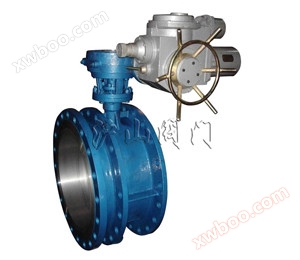
SD943 electric telescopic butterfly valve
2、 The electric telescopic butterfly valve adopts the standard design standard: GB/T12238-1989; JB/T8527-1997 Flange connection dimensions: GB/T9113.1
Product details
| product name: | Electric telescopic butterfly valve | PRODUCT MODEL: | SD943 |
| Drive mode: | electric | Connection form: | flange |
| structural style: | Triple eccentricity | Sealing material: | Hard alloy, stainless steel |
| Pressure Range: | ≤1.6MPa | Nominal Diameter: | DN50-DN2000 |
| Common materials: | Carbon steel, stainless steel | technical advice: |
1、 Overview of Electric Telescopic Butterfly Valve
electricFlexible butterfly valveSuitable for regulating flow and intercepting media on water and gas pipelines in food, medicine, chemical, petroleum, power, textile, papermaking and other industries with temperature ≤ 80 ℃ and nominal pressure ≤ 1.6MPa. It has the function of compensating for pipeline thermal expansion and contraction. Its main characteristics are as follows:
1. Novel and reasonable design, unique structure, light weight, easy operation, and rapid opening and closing;
2. In addition to regulating and intercepting the flow, compensating for the thermal expansion and contraction caused by pipeline temperature differences, the telescopic butterfly valve can also provide convenience for valve installation, replacement, and maintenance.
3. The sealing part can be adjusted and replaced, and the sealing performance is reliable.
2、 Electric telescopic butterfly valve adopts standard
Design standard: GB/T12238-1989; JB/T8527-1997
Flange connection size:
GB/T9113.1-2000; GB/T9113.2-2000
GB/T9115.1-2000; GB/T9115.2-2000
Structural length: GB/T12221-1989
Pressure test: GB/T13927-1992; JB/T9092-1999
3、 Electric telescopic butterfly valve actuator
1. Power supply: The motor is three-phase AC, 380V (special order 660V, 440V or 220V), 50Hz (special order 60Hz); Control line voltage 220V/50Hz (special order 60Hz); Remote control voltage 24VDC.
2. Working environment:
3. Environmental temperature: -20 to+60 ℃ (special orders -60 to+80 ℃)
4. Relative temperature: ≤ 90% (at 25 ℃)
5. Ordinary and outdoor types are used in places without flammable/explosive and non corrosive media; There are two types of explosion-proof products, d Ⅰ and d Ⅱ BT4. d Ⅰ is suitable for non mining working faces in coal mines; DIIBT4 is used in factories and is suitable for explosive gas mixtures in environments of IIA and IIB levels T1-T4 groups. (See GB3836.1 for details)
6 Protection level: IP55 for outdoor and explosion-proof types (IP67 can be customized).
7. Work schedule: Short duration of 10 minutes (30 minutes can be customized).
4、 Main technical parameters of electric telescopic butterfly valve
|
Nominal Diameter |
DN(mm) | 50~2000 | ||
|---|---|---|---|---|
|
nominal pressure |
PN(MPa) |
0.6 |
1.0 |
1.6 |
|
test pressure |
strength test |
0.9 |
1.5 |
2.4 |
|
Sealing test |
0.66 |
1.1 |
1.76 |
|
|
Airtight seal test |
0.6 |
0.6 |
0.6 |
|
|
Temperature |
≤80℃ |
|||
|
Applicable Medium |
Air, water, steam, gas, oil, etc. |
|||
|
Drive form |
Manual, worm gear transmission, pneumatic transmission, electric transmission. |
|||
5、 Main component materials of electric telescopic butterfly valve
|
Nominal Diameter |
DN(mm) | 50~2000 | ||
|---|---|---|---|---|
|
nominal pressure |
PN(MPa) |
0.6 |
1.0 |
1.6 |
|
test pressure |
strength test |
0.9 |
1.5 |
2.4 |
|
Sealing test |
0.66 |
1.1 |
1.76 |
|
|
Airtight seal test |
0.6 |
0.6 |
0.6 |
|
|
Temperature |
≤80℃ |
|||
|
Applicable Medium |
Air, water, steam, gas, oil, etc. |
|||
|
Drive form |
Manual, worm gear transmission, pneumatic transmission, electric transmission. |
|||
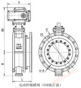
6、 Main external connection dimensions of electric telescopic butterfly valve

|
|
| Structural diagram of electric telescopic butterfly valve |
|
nominal |
External dimensions (reference value) | Flange size and bolt hole size (standard value) |
electric device model (Reference) |
|||||||||||||||||
|---|---|---|---|---|---|---|---|---|---|---|---|---|---|---|---|---|---|---|---|---|
| H | H1 |
design maximum length |
design minimum length |
design length |
A | B | 0.6MPa | 1.0MPa | 1.6MPa | |||||||||||
| mm | D | D1 | D2 | n-d | D | D1 | D2 | n-d | D | D1 | D2 | n-d | ||||||||
|
50 |
80 |
440 |
186 |
156 |
171 |
250 |
255 |
140 |
110 |
88 |
4-14 |
165 |
125 |
99 |
4-18 |
165 |
125 |
99 |
4-18 |
QB10-1 |
|
65 |
95 |
445 |
190 |
160 |
175 |
250 |
255 |
160 |
130 |
108 |
4-14 |
185 |
145 |
118 |
4-18 |
185 |
145 |
118 |
4-18 |
QB10-1 |
|
80 |
98 |
476 |
198 |
166 |
182 |
250 |
255 |
190 |
150 |
124 |
4-18 |
200 |
160 |
132 |
8-18 |
200 |
160 |
132 |
8-18 |
QB10-1 |
|
100 |
114 |
504 |
228 |
188 |
208 |
250 |
255 |
210 |
170 |
144 |
4-18 |
220 |
180 |
156 |
8-18 |
220 |
180 |
156 |
8-18 |
QB10-1 |
|
125 |
128 |
550 |
240 |
201 |
220 |
250 |
255 |
240 |
200 |
174 |
8-18 |
250 |
210 |
184 |
8-18 |
250 |
210 |
184 |
8-18 |
QB20-1 |
|
150 |
139 |
652 |
240 |
206 |
226 |
300 |
315 |
265 |
225 |
199 |
8-18 |
285 |
240 |
211 |
8-22 |
285 |
240 |
211 |
8-22 |
QB20-1 |
|
200 |
174 |
732 |
265 |
219 |
242 |
300 |
315 |
320 |
280 |
254 |
8-18 |
340 |
295 |
266 |
8-22 |
340 |
295 |
266 |
12-22 |
QB60-1 |
|
250 |
215 |
823 |
295 |
240 |
267 |
300 |
315 |
375 |
335 |
309 |
12-18 |
395 |
350 |
319 |
12-22 |
405 |
355 |
319 |
12-26 |
QB60-1 |
|
300 |
245 |
877 |
308 |
254 |
282 |
300 |
315 |
440 |
395 |
363 |
12-22 |
445 |
400 |
370 |
12-22 |
460 |
410 |
370 |
12-26 |
QB120-1 |
|
350 |
270 |
932 |
327 |
272 |
300 |
300 |
315 |
490 |
445 |
413 |
12-22 |
505 |
460 |
429 |
16-22 |
520 |
470 |
429 |
16-26 |
QB120-1 |
|
400 |
305 |
1047 |
368 |
308 |
338 |
300 |
315 |
540 |
495 |
463 |
16-22 |
565 |
515 |
480 |
16-26 |
580 |
525 |
480 |
16-30 |
QB250-1 |
|
450 |
325 |
1092 |
370 |
310 |
340 |
575 |
714 |
595 |
550 |
518 |
16-22 |
615 |
565 |
530 |
20-26 |
640 |
585 |
548 |
20-30 |
QB250-1 |
|
500 |
360 |
1182 |
392 |
332 |
362 |
575 |
714 |
645 |
600 |
568 |
20-22 |
670 |
620 |
582 |
20-26 |
715 |
650 |
609 |
20-33 |
QB250-1 |
|
600 |
445 |
1380 |
441 |
375 |
408 |
656 |
810 |
755 |
705 |
667 |
20-26 |
780 |
725 |
682 |
20-30 |
840 |
770 |
720 |
20-36 |
QB50 |
|
700 |
505 |
1502 |
460 |
400 |
445 |
656 |
810 |
860 |
810 |
772 |
24-26 |
895 |
840 |
794 |
24-30 |
910 |
840 |
794 |
24-36 |
QB50 |
|
800 |
560 |
1545 |
499 |
445 |
475 |
656 |
810 |
975 |
920 |
878 |
24-30 |
1015 |
950 |
901 |
24-33 |
1025 |
950 |
901 |
24-39 |
ZA60 |
|
900 |
630 |
1710 |
520 |
460 |
490 |
785 |
863 |
1075 |
1020 |
978 |
24-30 |
1115 |
1050 |
1001 |
28-33 |
1125 |
1050 |
1001 |
28-39 |
ZA60 |
|
1000 |
680 |
1805 |
600 |
530 |
565 |
785 |
863 |
1175 |
1120 |
1078 |
28-30 |
1230 |
1160 |
1112 |
28-36 |
1255 |
1170 |
1112 |
28-42 |
ZA60 |
|
1200 |
795 |
2096 |
675 |
571 |
623 |
785 |
863 |
1405 |
1340 |
1295 |
32-33 |
1455 |
1380 |
1328 |
32-39 |
1485 |
1390 |
1328 |
32-48 |
ZA120 |
|
1400 |
900 |
2296 |
760 |
684 |
722 |
790 |
1338 |
1630 |
1560 |
1510 |
36-36 |
1675 |
1530 |
1530 |
36-42 |
1685 |
1590 |
1530 |
36-48 |
ZA120 |
|
1600 |
1100 |
2720 |
860 |
770 |
815 |
868 |
1476 |
1830 |
1760 |
1710 |
40-36 |
1915 |
1820 |
1750 |
40-48 |
1930 |
1820 |
1750 |
40-56 |
ZA240 |
|
1800 |
1124 |
2830 |
930 |
830 |
880 |
868 |
1476 |
2045 |
1970 |
1718 |
44-39 |
2115 |
2020 |
1950 |
44-48 |
2130 |
2020 |
1950 |
44-56 |
ZA240 |
|
2000 |
1292 |
3120 |
1020 |
920 |
970 |
965 |
1600 |
2265 |
2180 |
2125 |
48-48 |
2325 |
2230 |
2150 |
48-48 |
2345 |
2230 |
2150 |
48-62 |
ZA240 |
7、 Precautions for installation and use of electric telescopic butterfly valve
1. The telescopic butterfly valve must be placed flat before installation and must not be bumped randomly.
2. The structural length of the telescopic butterfly valve is the minimum length when it leaves the factory, and during installation, it is pulled to the installation length (i.e. the design length).
3. When the length between pipelines exceeds the installation length of the expansion valve, please adjust the pipeline spacing and do not forcefully stretch the expansion valve to avoid damaging it.
4. The telescopic butterfly valve can be installed at any time. When used for temperature compensation, after the pipeline installation is completed, brackets need to be added at both ends along the axis direction of the pipeline to prevent the telescopic valve from pulling out. The support force of the bracket is calculated according to the following formula, and it is strictly prohibited to remove the bracket during operation.
5. When the telescopic butterfly valve does not perform temperature compensation and is only used for installation, replacement, and maintenance of the valve for convenience, a butterfly bolt can be used to limit and symmetrically clamp the telescopic butterfly valve to prevent the telescopic pipe from pulling out, damaging the telescopic butterfly valve and pipeline equipment or buildings. The bolt diameter can be calculated according to the flange bolt diameter, its bolt strength, and the test pressure and pipeline tension it can withstand, using the above formula. During operation, it is strictly prohibited to remove the limit bolt (bolts are provided separately)
6. It is strictly prohibited to dismantle and dismantle the telescopic butterfly valve at the pipeline construction site.
7. This scalabilityelectric butterfly valveThe processing is fine and the fit is tight. Please do not repeatedly elongate or shorten the telescopic butterfly valve on site. When installing the pipeline, it is required that the two ends of the expansion valve pipeline must be concentric, and the two flange surfaces on the pipeline must be parallel.
8. The flange fixing bolts should be symmetrically tightened, and do not forcefully tighten the flange fixing bolts on one side.
9. The expansion pipe is installed behind the valve.
10. The expansion part of the expansion valve shall not be installed at the corner or end of the pipeline.
Online inquiry
-
Contacts
-
Company
-
Telephone
-
Email
-
WeChat
-
Verification Code
-
Message Content
-