
VIP member
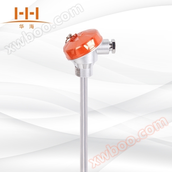
WRN-120/130 assembled thermocouple without fixed device
Prefabricated thermocouples can directly measure and connect various liquid, steam, gas media and solid surface temperatures ranging from 0 ℃ to 1800
Product details
WZP-120/130 assembled thermocouple without fixed device
High temperature temperature sensor | Stable performance, accurate measurement | Good pressure resistance | Good interchangeability
 
|
Working principle
Two conductors with different compositions are welded at both ends to form a circuit. The temperature measuring end is called the measuring end, and the wiring terminal is called the reference end. When there is a temperature difference between the measurement and reference ends, a thermal current will be generated in the circuit. When connected to a display instrument, the instrument will indicate the temperature value corresponding to the thermoelectric potential generated by the thermocouple.
Thermoelectric properties are a universal characteristic of matter, but only a pair of metal conductors with good linearity, stability, repeatability, high thermoelectric potential, easy standardization, abundant material resources, easy purification, and good corrosion resistance in the relationship curve between thermoelectric potential and temperature can become materials for making thermocouples. Thermocouples are widely used on-site temperature measuring instruments.
The thermoelectric potential of a thermocouple will increase as the temperature at the measuring end rises. The magnitude of the thermoelectric potential is only related to the material of the thermocouple conductor and the temperature difference between the two ends, and is independent of the length and diameter of the thermoelectric electrode.
 |
| Working principle diagram of thermocouple |
Nominal pressure of thermocouple
Generally refers to the static external pressure that the protective tube can withstand at working temperature without breaking. In fact, the allowable working pressure is not only related to the material, diameter, and wall thickness of the protective tube, but also to its structural form, installation method, insertion depth, as well as the flow rate and type of the measured medium.
Minimum insertion depth of thermocouple
It should not be less than 8-10 times the outer diameter of its protective tube (except for special products).
Structure of Thermocouples Product Structure
According to the temperature measurement principle of thermocouples, in addition to the two thermoelectric electrode materials, the basic thermocouple must also be made with measuring and reference ends at both ends of the thermoelectric electrode according to requirements, commonly known as the "hot end" and "cold end", which are the so-called "two ends".
According to the different uses of thermocouples, there are four forms of the hot end: insulated, multi branch insulated, shell connected, and exposed. The cold end has two forms: sealed and unsealed.
Thermocouples are generally composed of five parts. Two thermoelectric electrodes (or wires) are the core part of the thermocouple (the first part is the temperature measuring element), and the other parts are spread around it. In order to ensure that the thermoelectric potential in the circuit is not lost and the measured temperature signal is accurately transmitted, insulation materials must be used to ensure reliable insulation between the two thermoelectric electrodes except for the two endpoints and between them and the outside world (the second part is insulation materials); In order to protect the insulation material and thermocouple wires and extend the service life of thermocouples, protective sleeves (Part III protective sleeves) are generally designed; In order to facilitate installation and wiring, and to adapt to various usage scenarios, a fourth part wiring device and a fifth part installation fixing device are generally designed. These are the so-called 'Five Parts'. According to different purposes, the basic thermocouple (i.e. thermocouple core) that can measure temperature does not have protective tubes or installation fixtures. Prefabricated thermocouples are mainly composed of a junction box, protective tube, insulating sleeve, terminal block, and thermoelectric electrode, and are equipped with various installation and fixing devices.
 |
Selection of Temperature Measuring Elements for Thermocouples
| Thermocouple category | Graduation | Measurement range ℃ | Allowable deviation △ t ℃ | Performance characteristics | |
| advantage | disadvantage | ||||
| Nickel chromium nickel silicon | K | 0~1200 | ± 2.5 ℃ or ± 0.75% t | Good thermoelectric potential, good stability, and good oxidation resistance, making it a widely used temperature measuring element | Not suitable for reducing atmosphere, affected by aging changes and short-range ordered structural changes |
| Nickel chromium copper nickel | E | 0~800 | ± 2.5 ℃ or ± 0.75% t | Among existing thermocouples, they have high thermoelectric potential, high sensitivity, good linearity of two-stage non-magnetic thermoelectric potential, good stability, and good oxidation resistance, making them widely used temperature measuring elements | Not suitable for reducing atmosphere, low thermal conductivity, with slight hysteresis phenomenon. Not suitable for reducing atmosphere, affected by aging changes and short-range ordered structure changes |
| Copper Copper Nickel | T | —40~350 | ± 1 ℃ or ± 0.75% t | Can be used in reducing atmospheres, with good linearity of hot spot potential, good low-temperature characteristics, and good stability | Low operating temperature, easy oxidation of positive copper, large thermal conductivity error |
| Iron copper nickel | J | 0~800 | ± 2.5 ℃ or ± 0.75% t | Can be used in reducing atmospheres, with a higher thermoelectric potential than K | Iron is prone to rusting and has a large drift in thermoelectric properties |
| Nickel chromium silicon nickel silicon | N | 0~1200 | ± 2.5 ℃ or ± 0.75% t | Having all the advantages of K-type thermocouples, the short-range ordered structural changes have little impact | Not suitable for reducing atmosphere, affected by aging changes |
Product selection
Model representation
 |
Model representation Type specification
| Thermocouple category | PRODUCT MODEL | Graduation | Protective tube material | Temperature measurement range ℃ | Output |  |
| Single nickel chromium nickel silicon | WRN-130 | K | 304 | 0-800 | DIRECT | |
| Double branch nickel chromium nickel silicon | WRN2-130 | GH2520 | 0-1000 | |||
| Single nickel chromium nickel silicon | WRNB-130 | 304 | 0-800 | 4~20mA output | ||
| Double branch nickel chromium nickel silicon | WRNB2-130 | GH2520 | 0-1000 | |||
| Single nickel chromium nickel silicon | WRE-130 | E | 304 | 0-800 | DIRECT | |
| Double branch nickel chromium nickel silicon | WRE2-130 | GH2520 | 0-1000 | |||
| Single nickel chromium nickel silicon | WREB-130 | 304 | 0-800 | 4~20mA output | ||
| Double branch nickel chromium nickel silicon | WREB2-130 | GH2520 | 0-1000 | |||
| Single nickel chromium nickel silicon | WRC-130 | T | 304 | 0-800 | DIRECT | |
| Double branch nickel chromium nickel silicon | WRC2-130 | GH2520 | 0-1000 | |||
| Single nickel chromium nickel silicon | WRCB-130 | 304 | 0-800 | 4~20mA output | ||
| Double branch nickel chromium nickel silicon | WRCB2-130 | GH2520 | 0-1000 | |||
| Single nickel chromium nickel silicon | WRF-130 | J | 304 | 0-800 | DIRECT | |
| Double branch nickel chromium nickel silicon | WRF2-130 | GH2520 | 0-1000 | |||
| Single nickel chromium nickel silicon | WRFB-130 | 304 | 0-800 | 4~20mA output | ||
| Double branch nickel chromium nickel silicon | WRFB2-130 | GH2520 | 0-1000 | |||
| Single nickel chromium nickel silicon | WRM-130 | T | 304 | 0-800 | DIRECT | |
| Double branch nickel chromium nickel silicon | WRM2-130 | GH2520 | 0-1000 | |||
| Single nickel chromium nickel silicon | WRMB-130 | 304 | 0-800 | 4~20mA output | ||
| Double branch nickel chromium nickel silicon | WRMB2-130 | GH2520 | 0-1000 |
installation diagram
 |
Online inquiry
-
Contacts
-
Company
-
Telephone
-
Email
-
WeChat
-
Verification Code
-
Message Content
-